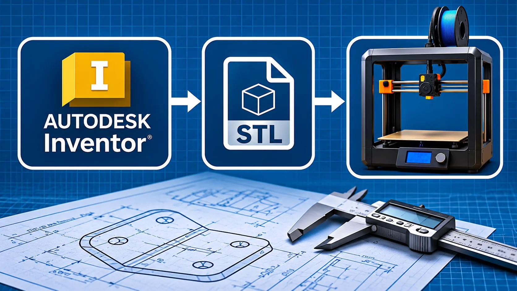
Autodesk Inventor can be used to design parts for 3D printing. It is particularly useful when you need a component with controlled dimensions, repeatable features and a model that can be revised later. But a good CAD model is not automatically a good 3D print.
This guide follows a simple example: a small mounting bracket with a base, an upright face and fixing holes. It covers what to think about in Inventor, how to export the model, and what your slicer must do before a printer can make the part.
1. Start with what the part must do
Before opening Inventor, decide what the bracket will hold, where it will attach and which dimensions are important. A sketch of the intended shape and a few key measurements can prevent unnecessary rework.
- Overall size: will it fit in the available space and on the printer's build plate?
- Fixings: what screw or bolt sizes will be used?
- Load: is this a lightweight cover, a positioning aid or a load-bearing component?
- Material and environment: consider temperature, sunlight, chemicals and mechanical demands.
For safety-critical or highly loaded components, a simple desktop print should not be assumed adequate without appropriate design, material selection and testing.
2. Create a parametric part in Inventor
Create a new part file and begin with a 2D sketch on a suitable origin plane. Draw the bracket's base profile, constrain the geometry and dimension it. Extrude the sketch to create the base thickness. Next, create the upright portion using another sketch and extrusion, or another modelling method suited to the shape.
Add the mounting holes using Inventor's hole features or appropriately dimensioned sketches. Use fillets where rounded transitions are useful. Keep important dimensions editable: this is one of the advantages of a parametric CAD system when a first print needs adjustment.
Good habit: give features meaningful names and avoid relying on approximate mouse placement when a dimension should control the design.
3. Think about wall thickness and strength
Very thin walls may not print reliably. The practical minimum depends on the printer, nozzle size, material and slicer settings. For example, a nominal 0.4 mm nozzle does not mean every 0.4 mm wall will be suitable: the number of perimeters, extrusion widths and geometry all matter.
Instead of assuming a universal minimum, check the intended printer and slicing profile. For a bracket, make the base and upright thick enough for the job, and consider a gusset or reinforcing rib at the corner. A smoothly rounded inside corner may also reduce a sharp stress concentration.
4. Allow clearance for parts that fit together
Holes, slots, lids and sliding fits are common reasons why a model that looks perfect on screen does not fit after printing. Printed dimensions vary with machine calibration, material shrinkage, print orientation and settings.
Design an intentional clearance rather than making two mating surfaces exactly the same nominal size. There is no single correct clearance for all printers: a small test coupon with several hole or slot sizes is often the most economical way to establish a working fit.
For accurate fastening, consider whether the design needs a clearance hole, a pilot hole, a heat-set insert or post-print drilling. The appropriate choice depends on the load and how often the joint will be assembled.
5. Consider print orientation while modelling
A 3D printer builds the part in layers. With common filament-based (FDM/FFF) printing, a part can be weaker between layers than within a layer, and some overhangs require supports. That makes orientation a design decision, not merely a slicer setting.
For our bracket, printing flat on the base may provide a stable contact area, but the upright portion and its loading direction still need consideration. Alternative orientations can change support requirements, surface finish, dimensional accuracy and strength. Compare them in the slicer rather than assuming one is always best.
6. Check the finished CAD geometry
Before export, inspect the model from several directions. Look for unintended gaps, extremely thin features, unsupported details, internal geometry and sharp corners. Check that the design is a proper solid body, not just a collection of surfaces.
Save the native Inventor part file as your editable master. A mesh export is useful for manufacturing, but it is not a replacement for the feature-based source model.
7. Export a printable mesh
For many 3D-printing workflows, the next step is to export the finished solid as an STL mesh. Inventor's available export commands and options can vary by version, so use the STL export facility in your installation and inspect the export settings.
- Confirm the intended units. STL does not reliably carry unit information, so a millimetre/inch mismatch can make the model dramatically too large or small.
- Choose a mesh quality fine enough to represent curves without obvious faceting, but avoid unnecessarily huge files.
- Export the correct solid body or bodies and confirm the result in the slicer.
Some workflows also support formats such as 3MF, which can retain additional information depending on the software. For a straightforward Inventor-to-slicer workflow, STL remains a common starting point.
8. Open the file in slicing software
Inventor creates the geometry; a slicer converts that geometry into the printer-specific instructions needed for the build. Import the STL into a slicer compatible with your printer and verify the displayed dimensions.
Choose the correct printer, material and print profile. Examine orientation, layer height, wall/perimeter settings, infill, supports and bed adhesion. Use the slicer's layer preview to inspect areas such as the fixing holes and the bracket's inside corner.
Do not confuse the roles: Inventor is the CAD design tool, the slicer prepares the print, and the printer produces the physical object.
9. Print a prototype and revise the model
The first print is a test, not necessarily the finished part. Check whether the bracket fits, whether fasteners pass through the holes, and whether any walls or corners appear weak. Measure critical features and record what needs changing.
Return to the Inventor model, update the dimensions or features, export a fresh mesh and repeat. This design–print–measure–revise loop is where parametric modelling is especially helpful.
Common beginner mistakes
- Designing walls or small details without considering the printer's capabilities.
- Forgetting clearances around mating parts and fixings.
- Exporting with the wrong units or an overly coarse mesh.
- Ignoring build orientation and the direction of applied loads.
- Assuming a slicer will automatically make an unsuitable design printable.
- Overwriting the native CAD master with an exported mesh.
Is Inventor the right CAD package for 3D printing?
Inventor is a strong choice for dimension-driven mechanical components, especially if you already use it for engineering design. For artistic sculpting, other tools may be more natural. For beginners who do not already have Inventor access, the licensing and learning commitment may make alternatives such as Autodesk Fusion or FreeCAD worth exploring.
The best tool depends on the part you are making and the software you can access, not on a claim that one CAD package is universally superior.
Final checklist before slicing
- Is the part the correct size and a valid solid?
- Are holes, clearances and wall thicknesses intentional?
- Have you considered print orientation, supports and likely loads?
- Have you saved the editable Inventor file?
- Does the exported mesh open at the correct size in the slicer?
Further reading
- AutoCAD vs Inventor: which should you learn?
- Which CAD software should you learn first?
- FreeCAD vs Autodesk Fusion for beginners
Editorial note: This is a general CAD-to-3D-printing guide, not a tested print profile or a claim that the example bracket has been physically manufactured and load-tested. Printer-specific settings should be checked against the manufacturer's guidance.